MV Switchgear
 M-TECH’s metal-clad switchgear with vacuum breakers provides centralized control and protection of medium voltage power equipment and circuits in industrial, commercial and utility installations involving generators, motors, feeder circuits, and transmission and distribution lines.
Vacuum CB switchgear is available in maximum voltage ratings from 3.3 kV through 38 kV, and interrupting ratings as shown below. M-TECH offers a total design concept of cell, breaker and auxiliary equipment, which can be assembled in various combinations to satisfy user application requirements.
Two-high breaker arrangements are standard up to 15 kV. One-high arrangements can be furnished when required.
4.76 kV, 8.25 kV, 15 kV, 27 kV, 38 kV
8.25 kV: Up to 63 kA
15 kV: Up to 63 kA
27kV: Up to 40 kA
38 kV: Up to 40 kA
4000A Forced cooled (5 KV and 15 kV)
1200A, 2000A, (27 kV)
600A, 1200A, 1600A, 2000A, 2500A (38 kV)
3000A Forced cooled (38 kV)
4000A (5 and 20 kV)
1200A, 2000A, 2500A, 3000A (33 kV)
Note: Continuous currents above 4000A — Contact M-TECH
Advantages:
M-TECH’s Electrical Sector has been manufacturing metal-clad switchgear for over 20 years. Hundreds of MV panels used in a wide variety of applications, have been setting industry performance standards for years. With reliability as a fundamental goal, M-TECH engineers have simplified the MV panel design to minimize problems and gain trouble-free performance. Special attention to material quality and maximum possible use was made of components proven over the years in M-TECH switchgear. Maintenance requirements are minimized by the use of enclosed long-life vacuum interrupters. When maintenance or inspection is required, the component arrangements and drawers allow easy access. Light weight simplifies handling and relocation of the breakers.
Standards :
M-TECH switchgear meets or exceeds IEC , ANSI/ IEEE C37.20.2 and NEMA ® SG-5 as they apply to metal-clad switchgear. Vacuum circuit breakers meet or exceed all IEC , ANSI and IEEE standards applicable to AC high voltage circuit breakers rated on symmetrical current basis.Metal-Clad Switchgear—Medium Voltage.
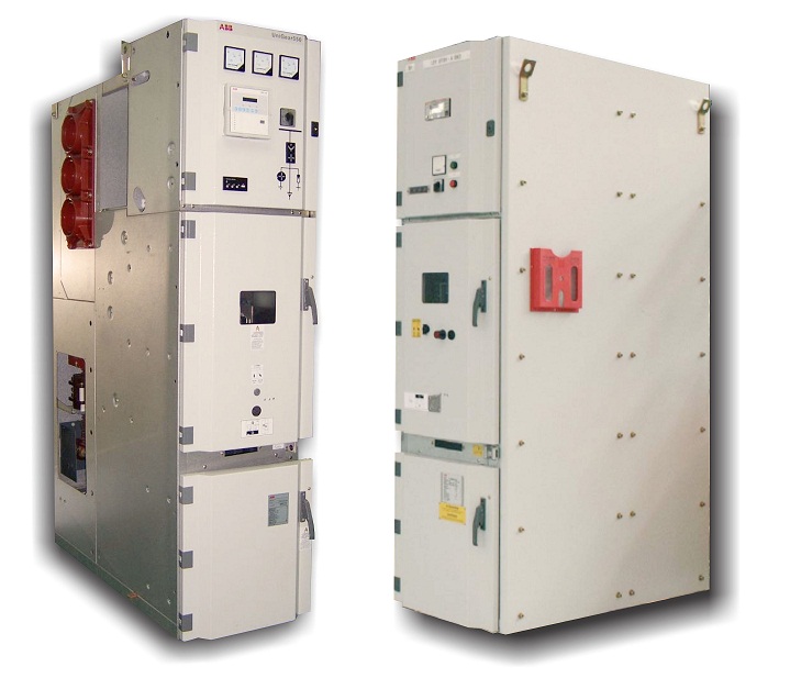
M-TECH’s VacClad switchgear is an inte-grated assembly of drawout vacuum circuit breakers, bus and control devices coordinated electrically and mechanically for medium voltage circuit protection and control. The metal-clad integrity provides maximum circuit separation and safety. All circuit breakers are equipped with self-aligning and self-coupling primary and secondary disconnecting devices, and arranged with a mechanism for moving it physically between connected and disconnected positions. All major primary components, such as circuit breaker, voltage trans-former, control power transformer, and buses are completely enclosed and grounded by metal barriers. A metal barrier in front of the circuit breaker and auxiliary drawer ensures that, when in the connected position, no live parts are exposed by opening the compartment door automatic shutters cover primary circuit elements when the removable element is in the disconnected, test or removed position. All primary bus conductors and connections are insulated with track-resistant fluidized bed epoxy coating for rated maximum voltage of the assembly. Mechanical interlocks are provided to maintain a proper and safe operating sequence Instruments, meters, relays, second-ary control devices and their wiring are isolated, where necessary, by grounded metal barriers from all primary circuit elements.Rear Compartments:
Rear of each structure is segregated into main bus and cable compartments by grounded metal barriers, as required for a given application. Access to main bus and power cable connections is provided from the rear through removable bolted covers or optional rear hinged doors. Cable trough (chimney) is provided to segregate upper and lower compartment power cables as required. All primary buses (main bus and line and load runbacks) are 100% conductivity copper, and insulated for rated maximum voltage of the assembly by flame retardant, track-resistant fluidized epoxy coating. The bolted bus joints are silver- or optionally tin-plated for positive contact and low resistance, with each joint insulated with easily installed boots. Bus supports between the adjacent units are made of high-impact, high-strength, track-resistant glass polyester at 5 and 20 kV, and cycloaliphatic epoxy at 20 and 33 kV. Adequate space is available for cable termination, bus duct connection, installation of zero sequence current transformers, and surge arresters. In two-high arrangement, power cables for each circuit are separated by metal barriers. A bare copper ground bus is provided in the rear of each structure, which extend the entire length of the switchgear. All control wiring is isolated from primary circuit elements by grounded metal-conduit or braided metal jacket, with the exception of short lengths of wire such as at instrument transformer terminals.Switchgear Structure
M-TECH’s compact metal-clad switchgear offers flexibility in locating the various elements of the apparatus, including the circuit breaker, auxiliary, and metering cells, within the structure lay-out. Circuit breakers may be located in either upper or lower cell positions, up to the maximum main bus self-cooled limit of the equipment (approximately 4,000 Amperes).Bus sectionalizing (tie)
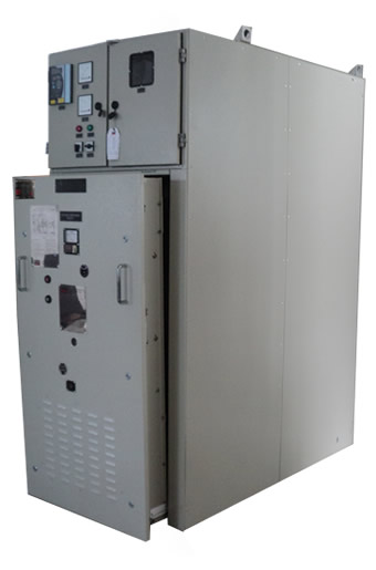
circuit breaker cells may be located on the upper or lower level, but must usually be located next to an auxiliary cell on same level to accommodate the transition bus work. All 2500 ampere circuit breakers are located on the bottom level of a cubicle with an upper cell that can be used for metering. Each vertical section may contain a main bus bar compartment and two cells for auxiliary devices and/or circuit breakers, including primary and secondary disconnects, instrument trans-formers, instruments and relays, secondary wiring and other components, as necessary. The additional vertical sections may be readily added in the future.Enclosure Design
The design of M-TECH MC switchgear incorporates maximum compartmentation. This means the complete enclosure of all live parts and positive segregation of primary circuits to retard the spread of faults to other sections of the apparatus. Hinged doors or removable plates permit easy access to all compartments. All metal barriers are suitably grounded. Steel barriers extend the full height and depth of each vertical section for isolating adjacent sections. Each cubicle is equipped with a continuous copper ground bus which extends throughout the entire switch-gear lineup. Circuit Breaker metal clad switchgear employs a reinforced sheet steel cell en-closure with provisions for the appropriate circuit breaker, including (but not limited to).A hinged front door, inter-compartment and inter-unit barriers, stationary primary disconnects, circuit breaker racking mechanism, circuit breaker inter-locking devices, primary shutter mechanism, draw out guide rails where required, and secondary control circuit connectors. Provisions are provided for instruments and relays, control wiring, terminal blocks, current transformers, and secondary control circuit cutouts. Breaker Interchangeability.
M-TECH,s MC type switchgear cubicles and removable circuit breaker elements are built using modern construction aids so Typical Cell—
Note: Shutters and barriers removed